

These are mechanical switches that protect against short circuits and over-currents in circuits supplied with direct current. They are designed to break the current flow in DC electrical systems in the event of a fault.
They apply mechanisms that can limit the current and also extinguish arcs caused by over-current. Through this, the differential timing of the circuit is greatly improved.
Circuit Breaker for DC Basics
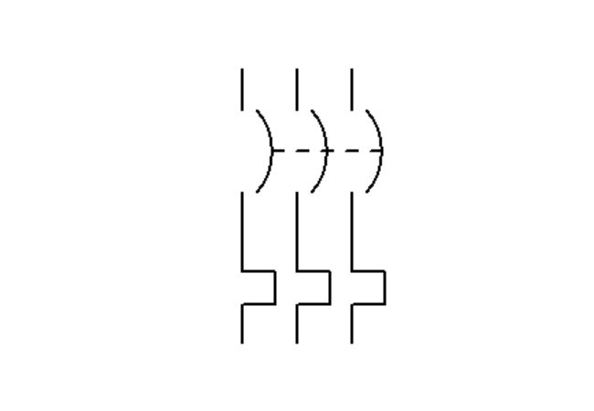
DC Circuit Breaker Symbol
We use these symbols mainly in electrical circuits.
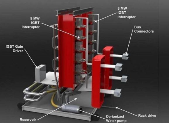
· DC Circuit Breaker Wiring Diagram
However, for a wiring diagram, you will find a 3D image such as this:

Function of Circuit Breaker in DC Systems
It is clear from their name that we use such electrical breakers to protect systems that use direct current to operate. Such systems have a constant voltage output unlike AC systems.
They use a combination of magnetic and thermal principles to protect the DC Systems. If the current goes beyond the rated value, the breaker is tripped using thermal protection.
It is designed to hold out momentarily any current fault that occurs within the circuit. It also serves to rapidly put out any arcs brought about by excess voltage.
The breaker thermal protection is a fail-safe against any overload current in the system. When dealing with strong fault currents, the rapid magnetic protection trips the breaker.
Having a constant current flowing in the DC Circuits means that the contacts must be fully open beyond their limits. This is to ensure that the flow of the excess current is fully interrupted.
This means that the breakers guard the DC System against any faults or short circuits. Such short circuits tend to be greater than the overload.
Types of DC Circuit Breakers
DC Arc Suppression Circuit Breakers
When it comes to extinguishing Arc Suppression, DC Arcs are the most difficult. We supply Direct Current continuously meaning it is very stable on a very wide gap.
To reduce the Arcing effect, we have to ensure the switching mechanism have to separate the contacts very quickly. This should create an air gap that on opening will extinguish the arc.
The contacts on the breaker need to have extremely rapid motion to avert the same problems they face while opening them. The manufacturer always indicates the DC Ratings on the breaker.

Any short circuit on this breaker means the operating current increases to become the short circuit current. All this is reliant on the short-circuit loop inductance and resistance.
High-Speed DC Circuit Breaker
These breakers are mainly applied in traction substations and units. They are designed to cut off the current just before the maximum rated value is achieved.
When a short circuit occurs, the breaker is triggered by the rising current levels beyond the rated value. This results in the current being limited and eventually cut.

DC Solid State Circuit Breaker
This breaker is an advanced replacement of the electromechanical breakers. It replaces the moving parts with semiconductors used in power control with rapid current interruption.
With advanced software technology, they can clear faults in seconds after very fast interruptions. They are mostly used in electrical grids with energy storage systems to reduce the effect of downtime due to faults.
Arc flashes don’t occur in them during interruptions. This is because zero energy is released.
High Voltage DC Circuit Breaker
The HVDC breaker serves the sole purpose of fault current protection in high-voltage DC Circuits. It is worth noting that the current and voltage in DC circuits is never zero.
This means that during contact separation, the current and voltage is usually very high between them. The contacts will end up overheating due to arcing and destroying the breaker.
To counter this, we introduce a low-current circuit parallel to this breaker. To break the circuit, it will create an artificial zero current in the circuit.

Since we know the current and voltage level to be directly proportional to the arc strength, we use an external circuit. This will break the circuit just after reducing the fault current to zero.
Magnetic DC Circuit Breaker
This is a form of over-current protection device. It is designed in such a way that miniature magnets inside it are used to close and open the contacts.
It is composed of an enclosed wire coil that encircles a plunger made of iron. The plunger also has the contacts fixed on it.
When current is introduced to the coils, the contacts are drawn towards them. The solenoid contacts are closed and opened with this mechanism.

When the rated current value is exceeded, the trip lever is triggered by a very strong magnetic attraction. This opens the circuit and it can be closed by resetting the trip lever handle after removing the overload.
Thermal DC Circuit Breaker
It uses a latch mechanism that contains a bimetallic strip connected to it. The bimetallic strip reacts to heat by expansion of its two different metal components at different rates.
The circuit is opened when the bimetallic strip bends away from the contact. Its direct heating comes from the circuit current and indirectly from elevated temperatures from high circuit currents.
To reset the circuit breaker using its push button, you have to let the bimetallic strip cool down. This happens at normal room temperatures.

Thermal-Magnetic DC Circuit Breaker
This breaker applies two mechanisms. Overload protection is achieved by thermal tripping while magnetic tripping prevents short circuits.
We can alternatively call them inverse-time breakers. As the name implies, a higher overload will shorten the opening time for the breaker.
Heat is produced by the excess current in the event of an overload. The bimetallic element picks this up and the breaker trips when its rating is exceeded.
In the event of a short circuit, the electromagnetic sensor detects the fault current. It then responds by disconnecting the circuit.
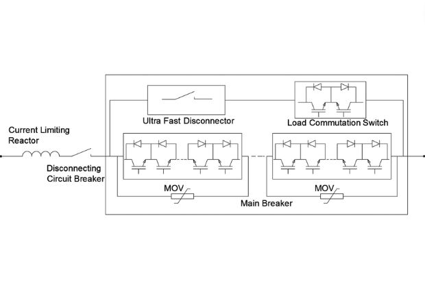
Hybrid DC Circuit Breaker
This is a DC Breaker having three separate branches that are configured in parallel to carry out different breaker tasks. The first branch has a mechanical switch used in conveying nominal current.
It also has contacts made of metal that act like mechanical circuit breakers by conduction losses. The second branch carries out efficient switching operations using semiconductors.
The sole purpose of the third branch is to inhibit transient voltages. It is made of metal oxide varistors (MOV) and they also take up the system’s magnetic energy.
Number of Poles
2 Pole DC Circuit Breaker
It contains two poles and protects circuits from short circuits with the ability to isolate loads. It is commonly used in energy storage and is normally positioned between inverters and batteries.
4 Pole DC Circuit Breaker
They are uniquely designed with one neutral pole while other poles provide circuit protection. It trips and disconnects all the poles immediately after it detects improper current.
It is not sensitive to polarity with applications in three and four-phase wire distributions. It is important in places using electrical equipment like hospitals that require protection.
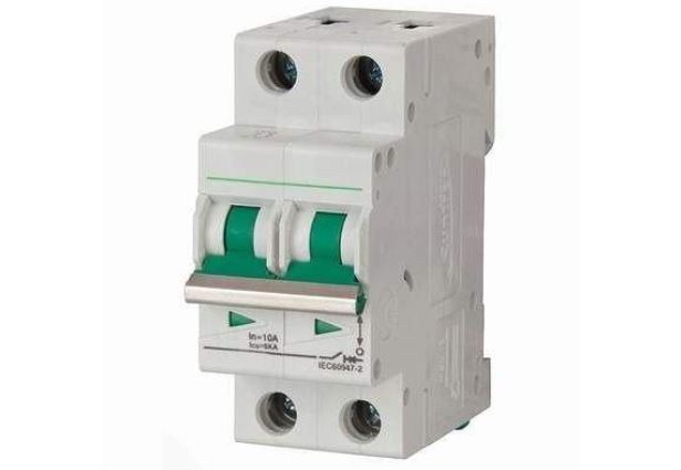
DC Mini Circuit Breaker/DC Miniature Circuit Breaker
The design of the DC MCB is specific circuit breakers using direct current. It protects the electrical equipment from short circuits and over-currents.
It should be noted that its operation and functions are similar to an AC MCB. However, the areas of application differ.
The application of DC MCBs is mainly on systems working with direct current such as solar photovoltaic (PV). The breaker operates within a voltage range of between 12-500V.
The breaker has the positive and negative symbols marked on it. Additionally, we have the current direction indicated on them too.
DC Molded Case Circuit Breakers
We mostly use the DC MCCB in applications that require storage of energy. They are also the best choice for use in industrial DC Circuits.
DC Air Circuit Breaker
Just like the other breakers, it offers protection against over-current and short circuits in electrical devices. The protection mechanism is mainly by using a blast of air to limit the effects of arcing.
Its working principle is not the same as the regular circuit breakers. Strange but have a look at this, it generates an arc voltage when interrupting an arc instead of giving a supply voltage.
Arc voltage is the least voltage needed to sustain an arc. Among the ways it increases the voltage is by ripping the arc into various series.
It can also lengthen the arc path therefore increasing its resistance. This will require additional arc voltage across the path therefore increasing in voltage.
The breaker has two pairs of contact with the main copper contact carrying current. The other contact is made of carbon.
The main contact is the first to open immediately after the breaker opens while the arc contact remains intact. Arcing begins instantly upon the separation of the contacts.
Parts of Circuit Breaker for Direct Current
The components of various types of circuit breakers are basically the same.
Let’s have a look at them in detail:
Frame – it is usually very strong and rigid. Its main purpose is to protect the internal components against environmental extremities. It also provides insulation.
Toggle/Handle – normally used to close or open the DC breaker. For larger breakers, the operators can use a 2-step process for protection.
Contacts – they are responsible for the flow of current once they are connected. In breakers for low voltage, the contacts are located in the chamber housing the arc interruption.
Arc extinguisher – when the breaker trips due to a fault, it extinguishes the arc generated. Since we can’t prevent arcs from occurring, the best the breaker can do is to control them.
Trip Unit – when the short circuit or overload is long, the operating mechanism is opened by the trip unit. They can either be electronic or operate electro-mechanically.

DC Circuit Breaker Working Principle
The main function of the DC Breaker is protect the circuit from either fault currents or over-currents. It uses either the thermal or magnetic protection mechanisms to achieve this.
When there is an over-current, the DC Breaker is tripped by thermal protection. This means that the electric current went beyond the rated breaker value.
It has bimetallic strips made of two different metals that expand when heated. The difference in their expansion make the bimetallic strip bend and breaks contact with the contactor.
The Thermal protection mechanism only works for overload currents. This implies that it exceeded the conventional operating current.
The magnetic protection is used when there is heavy fault current in the circuit. It will trip the DC Circuit Breaker and the action is rapid and instant.
The circuit breaker can be switched back on using the handle or toggle. This should be done after rectifying the overload or short circuit.
DC Circuit Breaker Rating
When you want to settle on an appropriate DC Circuit, you have to take into account your electrical systems total voltage rating. You can calculate such a rating by taking the highest applicable from all ports.
When calculating the voltage, you additionally need to consider how you will integrate the breaker and voltage distribution. The voltage rating of the breaker should be sufficient enough to handle all the end application demands.
The breakers amperage is also very important in its rating. Based on the load requirements, the breaker must operate at 100%.
However, you can achieve maximum operation by choosing a breaker with 120% current of the load. This will assist in cushioning the heat emitted by the power system.
DC Circuit Breaker Sizing
Sizing a DC Circuit Breaker can prove to be a very daunting task. However, it’s never an impossible task.
We are fully aware that the breaker size has to be large enough to accommodate the required load current. Under sizing a breaker means you run the risk of causing electric fire.
Not to worry. A few rules and you can comfortably size your DC Breaker.
They are:
80% Breaker Rule
The rule basically says that you can only have 80% of the currents rated ampacity. Let’s take an example of a 40A breaker.
The safest maximum current you can allow is 32A. This safety measure prevents the breaker from burning.
Calculating Amps from Wattage
All electronic devices you will use have a rated wattage indicated. Let’s take an example of a 2000W toaster.
Since breaker sizing is all about Amps, you will need to convert the wattage to Amps. Assuming your supply it with 240V, current will be 2000W/240v giving 8.33A.
If you’re okay with keeping up with these two rules, then calculating the breaker size is a walk in the park. Now to calculating the breaker size by using an example.
Let’s take the 2000W toaster drawing 8.33A. Taking the 80% breaker rule, that gives us the 8.33A.
To arrive at the circuit breaker size, we take a 1.25 factor and multiply it by the amp drawn. That puts the minimum breaker size at 8.33A × 1.25 = 10.42 Amps.
Since the breaker ampacity should be minimum of 10.42, we can as well use a breaker size of 15 Amps. In summary, we will require a 15A breaker for the toaster 2000W toaster supplied by240V.
This how we can manually arrive at the breaker size. However, there are modern dynamic calculators which are much faster and easier.
If you end up with bigger amp draws, you can have a couple of 30 or 50A breakers in parallel. This will the overall breaker ampacity.
Thermal Magnetic Tripping in Circuit Breaker for DC
In the event that the rated current value is surpassed in an electric circuit, the breaker is tripped by thermal protection. The thermal breaker has bimetallic strips which have two metals that expand differently.
The heat from the excess current makes the bimetallic strip bend and break contact with the contactor. This breaks the circuit by cutting the current flow.
The tripping is rapid because the heat generated by the current is too much for the bimetallic strip. This is the breakers protection mechanism against overload currents that exceed the operating current.
DC MCB Circuit Breaker vs Molded Case Circuit Breaker (MCCB)
The abbreviations may have a striking resemblance but let that not fool you. Let’s have a look at some of their difference to better understand their applications.
For starters, their capacity is what majorly differentiates them. The current rating of MCBs is less than 100A their interrupting rating not exceeding 1800A.
Furthermore, we mostly apply them in low circuits. This makes it impossible for us to adjust their trip characteristics.
On the other hand, we can easily adjust the trip characteristics of the MMCBs. Because we majorly use them in high circuit applications, they give an amp range of about 10-2500A depending on application.
Their range of interrupting current is quite impressive at between 10000-200000A. They easily respond to remote commands for motor operations.
DC Vs AC Circuit Breaker
Both DC and AC have the same operational principles with difference coming in the electric current. They both use magnetic and thermal protection techniques but on direct and alternating currents.
Also worth noting is the arc extinguishing point in both of them which is lower in AC breakers. This is because the continuous voltage in DC ensures a constant arc that is hard to interrupt.
Consequence? We have extra arc extinguishing measures in DC breakers. The arc is prolonged and dissipated to make interruption much simpler.
On the contrary, AC Circuit Breakers have it very easy with arc interruption. The amplitude vibration ensures every cycle gets to zero where interruption easily takes place.
Applications of Circuit Breaker in DC Systems
· Circuit Breaker for DC Power Transmission
High Voltage DC breakers offer protection when power transmission is over long distances. The terminals required when converting AC/DC or DC/AC cost a lot and have to be protected. Fault currents can cause damage to any connected equipment hence a breaker is necessary.
· DC Motor Circuit Breaker
The breakers protect DC Electric motors having various applications. Most of them are automated with rapid response times with control circuits using DC. All these require a DC breaker for protection.
· DC Solar Circuit Breaker
Solar panels are usually assembled in series circuits which may be several. All the circuits must have a DC Circuit breaker protection because they are very crucial in the whole circuit.
How to Choose Circuit Breaker for DC
You will find various DC Circuit Breakers available in the market. With such options, it becomes easier for you to make a choice.
However, ask yourself some of these questions before settling for the most appropriate:
- What is the current rating of your intended device?
- How many poles do you require for your breaker?
- What is the voltage requirement for your device?
- What is your circuits total current?
- What are your atypical operating conditions?
FAQs
· Can AC Circuit Breakers be used in DC Systems?
When we consider AC and DC systems, we can conclude that the heating effect for both of them is the same. However, the same RMS values, still contain varied parameters.
Let’s take an example an AC and voltage. Their effect on a circuit is different from a DC supply having the same voltage.
Hence, making it impractical to use AC breakers in such circuits. The same principle applies to the use of DC breakers in AC circuits.
Now let’s dig into the facts in play here.
Additionally, considering the same voltage supply, usually the AC systems will require better insulation compared to the DC.
It implies – there will be different reactions when evaluating the insulation materials, especially on exposure to the rated and opposing voltage.
DC breakers have a constant value of current with no frequency.
Subsequently, the direction is not affected by the current or voltage. Consequence? The breaker contacts will melt faster when a DC breaker is used in an AC circuit.
· Arcing In DC Breakers Vs in AC Breakers
When we apply a DC Breaker to break a circuit, the contacts experience a constant flow of electrons. This is enhanced by a thrust forward from the applied voltage.
The effect is the generation of arc. The momentum of the electrons makes this Arcing stronger compared to AC Breakers.
Additionally, the electron supply in AC breakers has an easy flow. You should keep in mind the unsteady state of the current and applied voltage.
This means that they have amplitude fluctuation from peak to peak. The peaks are positive to zero then to negative and back to zero.
The result is the generation of momentum caused by the vibration distortion. This makes the generated Arc in AC weaker than the one created in DC Breakers.
· DC circuit Breakers Directional?
Normally, we have current in DC circuits flowing in only one direction. This means that the DC breaker also has to be unidirectional.
That ensures that the breaker only allows the flow of charge in only the specified direction. When we reverse the polarity, we most likely will damage the electrical devices with serious safety issues.
The DC breakers are designed in such a way that the current can be interrupted by arc voltage. This occurs when the currents are low.