يمكن الإشارة إلى مفتاح عزل التيار المستمر (DC) بشكل بديل باسمقاطع التيار المستمرهو جهاز كهربائي يستخدم في عزل مصدر طاقة التيار المستمر بشكل آمن عن النظام الكهربائي. فهو يسمح لك بقطع مصدر الطاقة المستمر مما يسمح بتنفيذ عمليات الصيانة أو السلامة.
مزايا مفتاح عزل التيار المستمر
توفر مفاتيح عزل التيار المستمر العديد من المزايا في تطبيقات التيار المستمر المختلفة مثل الأنظمة الكهروضوئية. إن اتباع الإرشادات الصحيحة عند استخدام مفاتيح عزل التيار المستمر يضمن الأداء الأمثل والموثوقية مما يسمح بتراكم هذه الفوائد.
تتم مناقشة بعض المزايا الرئيسية لمفاتيح عزل التيار المستمر على النحو التالي:

- أمان
هذه هي الفائدة الأساسية لمفتاح عزل التيار المستمر. يوفر هذا الجهاز الكهربائي وسيلة موثوقة لقطع مصدر الطاقة المستمر عن الحمل. ونتيجة لذلك، فإنه يضمن العمل الآمن والخالي من المخاطر على النظام مما يمنع حدوث صدمة كهربائية أو إصابة.
- الامتثال للرموز الكهربائية
يضمن استخدام مفاتيح عزل التيار المستمر في التركيبات الامتثال للوائح مما يضمن سلامة النظام وموثوقيته بشكل عام.
- العزل الخطأ
عندما يحدث عطل في نظام التيار المستمر، يتدخل مفتاح العزل عن طريق فصل مصدر الطاقة وعزل العطل. وهذا بدوره يحتوي على الأعطال ويقلل من تأثيرها، مما يحسن من موثوقية النظام ويقلل من خطر تلف المكونات.
- التشغيل عن بعد
مفاتيح كهربائية عازلة للتيار المستمر إن القدرة على التشغيل عن بعد تمكن من التحكم المريح والفعال من غرفة التحكم المركزية. وتعتبر هذه القدرة مفيدة بشكل خاص في التركيبات واسعة النطاق التي تحتوي على مفاتيح متعددة تتطلب التحكم المتزامن أو الاستجابات السريعة.
- إغلاق الطوارئ
يعد مفتاح عزل التيار المستمر مفيدًا في حالات الطوارئ مثل حدوث عطل كهربائي أو حريق. ويمكن إيقاف تشغيله بسهولة لإيقاف إمداد الطاقة مما يقلل من فرصة المخاطرة والمزيد من الضرر.
- التكامل مع أجهزة الحماية
يمكنك دمج مفاتيح عزل التيار المستمر مع أجهزة حماية أخرى مثل قواطع الدائرة والصمامات مما يعزز الحماية الشاملة للنظام. يسمح هذا التكامل بمزيد من الحماية من الأعطال الكهربائية مثل التيار الزائد والدوائر القصيرة.
مخطط توصيل عازل التيار المستمر
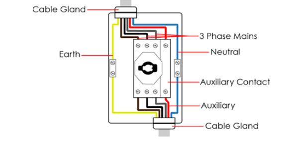
قد يختلف تكوين مخطط توصيل مفتاح عازل التيار المستمر حسب عدة أسباب. وتشمل هذه الأسباب نوع التطبيق والمواصفات مثل عدد الأقطاب وتصنيف الجهد وتصنيف التيار.
عند توصيل مفتاح عزل التيار المستمر، استخدم الكابلات المناسبة لمفتاح عزل التيار المستمر مع مراعاة الحجم والنوع. تأكد أيضًا من العزل المناسب وتأمين جميع التوصيلات قبل تركيب مفتاح عزل التيار المستمر وفقًا لدليل التركيب الخاص بالشركة المصنعة.
وظيفة مفتاح عزل التيار المستمر
الوظيفة الأساسية لمفتاح عزل التيار المستمر هي ضمان عدم تدفق الطاقة الكهربائية إلى النظام أو المعدات المتصلة. إنها آلية أمان لحماية كل من الأفراد والمعدات من المخاطر الكهربائية المحتملة.
عن طريق فصل مصدر الطاقةيمنع مفتاح العزل تشغيل النظام عن طريق الخطأ، وبالتالي يقلل من خطر التعرض لصدمة كهربائية.
أنواع مفاتيح عزل التيار المستمر
تتوفر عدة أنواع من مفاتيح عزل التيار المستمر بناءً على معلمات مثل تصنيف الجهد، وتصنيف التيار، وعدد الأقطاب. كما يمكن أن تختلف تصميمات مفاتيح عزل التيار المستمر أيضًا وفقًا للشركة المصنعة والتطبيق.
تتضمن بعض الأنواع الشائعة ما يلي:
مفتاح عزل التيار المستمر أحادي القطب
هو النوع الأكثر شيوعًا والذي يتكون من قطب واحد قادر على قطع تدفق التيار في موصل واحد. يستخدم في أنظمة التيار المستمر ذات الجهد المنخفض، مثل تركيبات الطاقة الشمسية الصغيرة أو المعدات الإلكترونية.
مفتاح عزل التيار المستمر متعدد الأقطاب
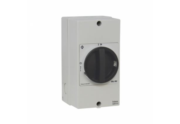
تحتوي هذه العناصر على مجموعات متعددة من جهات الاتصال (الأقطاب) التي يمكن أن يؤدي عملها المتزامن إلى مقاطعة تدفق التيار في موصلات متعددة. وتستخدم هذه العناصر في أنظمة التيار المستمر ذات قيم الجهد الأعلى والتطبيقات التي تتطلب عزل دوائر متعددة في وقت واحد.
يمكن أن تكون مفاتيح العزل متعددة الأقطاب للتيار المستمر ثنائية القطب (زوجان من جهات الاتصال)، أو ثلاثية الأقطاب، أو حتى رباعية الأقطاب. يستخدم الفاصل ثنائي القطب موصلًا موجبًا وآخر سالبًا، بينما يستخدم الفاصل ثلاثي الأقطاب في تطبيقات الطاقة ثلاثية الطور للتيار المستمر.
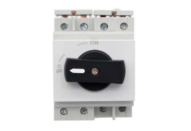
يحدد عدد الأقطاب مستوى العزل والتحكم المقدم حيث يضمن فتح جميع الأقطاب العزل الكامل. حدد قاطعًا بعدد الأقطاب المناسب بناءً على متطلبات التطبيق والدوائر التي تحتاج إلى فصل.
بناءً على تصنيف الجهد
يمكن أيضًا تصنيف مفاتيح عزل التيار المستمر وفقًا لتصنيفات الجهد الخاصة بها إلى جهد منخفض وجهد مرتفع. تتعامل مفاتيح فصل الجهد المنخفض مع أنظمة التيار المستمر ذات متطلبات الجهد المنخفض التي تتراوح عادةً إلى مائة فولت. وهي شائعة في مجموعات البطاريات وأنظمة الطاقة المتجددة الصغيرة الحجم.
تتعامل أجهزة فصل الجهد العالي مع متطلبات الجهد في أنظمة التيار المستمر المصنفة على أنها تصل إلى عدة كيلوفولت وحتى ميجافولت. وتُستخدم هذه الأجهزة في أنظمة نقل التيار المستمر ذات الجهد العالي، وشبكات توزيع التيار المستمر، ومحطات الطاقة الكهروضوئية التي تتضمن بنية تحتية معقدة.
بناءً على التصنيف الحالي
توجد مفاتيح عزل تيار مستمر منخفضة وعالية بناءً على قدرتها على التعامل مع التيار. تتعامل مفاتيح عزل التيار المنخفض مع تيارات منخفضة تتراوح من بضعة مللي أمبير إلى مئات الأمبير. تُستخدم هذه المفاتيح في دوائر التيار المستمر منخفضة الطاقة مثل أجهزة الاستشعار وبعض أنظمة الطاقة الشمسية والإلكترونيات الخاصة بالسيارات.
تتعامل مفاتيح عزل التيار المستمر عالية التيار مع تيارات كبيرة تصل إلى آلاف الأمبيرات وتتميز بتصميم قوي وتقنية متقدمة لقمع القوس الكهربائي. تتضمن بعض التطبيقات محطات شحن المركبات الكهربائية وأنظمة الطاقة المتجددة ومراكز البيانات.
مفتاح عزل التيار المستمر عند انقطاع الحمل
تعمل مفاتيح عزل التيار المستمر هذه على قطع تدفق التيار بأمان في ظل ظروف الحمل دون التسبب في حدوث قوس كهربائي مفرط أو تلف جهة اتصال المفتاح. تُستخدم هذه المفاتيح عادةً في تطبيقات التيار المستمر ذات التيار العالي مع الأمبيرات التي تتراوح بين المئات والآلاف، مثل أنظمة الطاقة الكهروضوئية واسعة النطاق.
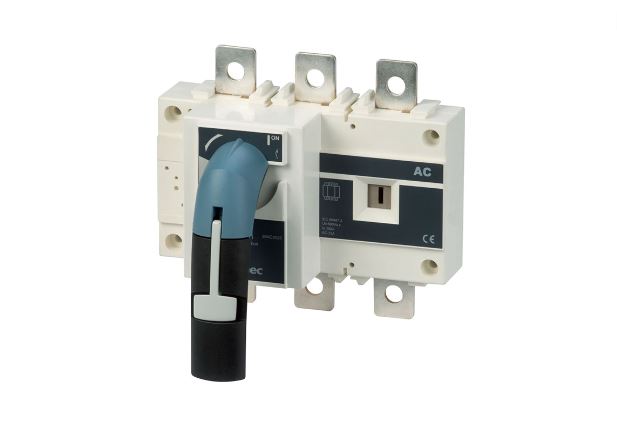
مفتاح عزل التيار المستمر بدون انقطاع الحمل
بالنسبة لهذا النوع من مفاتيح عزل التيار المستمر، فإن استخدامها الأساسي هو مقاطعة تدفق التيار في ظل ظروف عدم التحميل. فهي لا تستطيع التعامل مع التيارات العالية أو انقطاع الدوائر الحية المستخدمة بدلاً من ذلك في أنظمة التيار المستمر ذات الجهد المنخفض.
أجزاء مفتاح عزل التيار المستمر
يتكون مفتاح عزل التيار المستمر من أجزاء مختلفة تم تكوينها بطرق مختلفة حسب الشركة المصنعة والتطبيق. ومع ذلك، يتميز مفتاح عزل التيار المستمر عادةً بما يلي:
- المرفق: هذا هو الغلاف الخارجي الذي يؤمن ويحمي المكونات الداخلية لمفتاح عزل التيار المستمر وهو مصنوع من مواد عازلة.
- جهات الاتصال: تعمل كعناصر توصيل للقاطع والتي تعمل على توصيل أو قطع التوصيل الكهربائي. يوجد عادةً مجموعتان من جهات الاتصال: جهات الاتصال الرئيسية التي تتعامل مع تدفق التيار الأساسي وجهات الاتصال المساعدة للتحكم والإشارة.
- تجهيزات التشغيل: هو نظام يدوي أو آلي يفتح ويغلق جهات الاتصال باستخدام الرافعات أو المحركات الكهربائية على التوالي.
- اتصالات المحطة الطرفية: تقوم هذه العناصر بتوصيل مفتاح عزل التيار المستمر بالدائرة التي توفر الواجهة الكهربائية للموصلات الواردة والصادرة. وهذا يسمح بتدفق التيار.
- المظلات القوسية: تؤدي حركة التلامس إلى حدوث قوس كهربائي بسبب انقطاع تدفق التيار. تعمل أنابيب القوس التي تتكون من امتدادات تشبه الألواح على إطفاء هذا القوس عن طريق إنشاء مسار للسفر.
- أجهزة التحكم والحماية: تسمح أجهزة التحكم مثل المفاتيح المساعدة بنقل ردود الفعل أو الإشارات الخاصة بالتبديل. توفر أجهزة الحماية مثل الصمامات أو قواطع الدائرة حماية الدائرة من التيارات الزائدة.
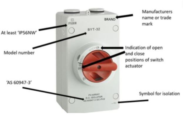
كيف يعمل مفتاح عزل التيار المستمر
يتضمن مبدأ عمل مفتاح عزل التيار المستمر فتح وإغلاق جهات الاتصال لعزل الدائرة عن مصدر الطاقة الخاص بها. يتم وصف تفصيل العملية أدناه:
- في البداية، يكون مفتاح عزل التيار المستمر في وضع مغلق مع توصيل جهات الاتصال وتوصيل التيار عبر الدائرة.
- لكي تتمكن من عزل الدائرة، يمكنك تنشيط آلية التشغيل يدويًا عن طريق تحريك الرافعة أو عن بعد عبر وسائل آلية.
- تفصل هذه العملية جهات الاتصال عن طريق إنشاء فجوة هوائية تعمل على مقاطعة التيار بشكل فعال اعتمادًا على تصنيفات الجهد أو التيار. قد يؤدي فصل جهات الاتصال إلى توليد قوس كهربائي يمكن إخماده باستخدام مزالق القوس.
- يشير الفصل الكامل إلى وضع مفتوح يتم فيه عزل الدائرة بشكل فعال عن مصدر الطاقة المستمر.
- لاستعادة الطاقة، قم بتنشيط آلية تشغيل المفتاح في الاتجاه المعاكس لإعادة الاتصال وإكمال الدائرة.
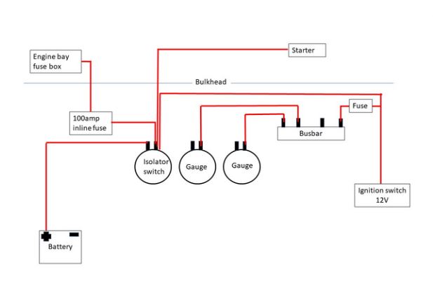
معلمات أداء مفتاح DCIsolator
تحدد معلمات الأداء الخصائص التشغيلية وقدرات مفتاح عزل التيار المستمر. تساعد هذه المعلمات في تقييم الأداء والموثوقية والملاءمة لتطبيقات محددة.
i. جهد التشغيل
يشير إلى الحد الأقصى للجهد الذي يعمل مفتاح عزل التيار المستمر تحته بأمان ويجب أن يتطابق مع جهد النظام أو يتجاوزه. قد يؤدي تجاوز الحد الأقصى لجهد التشغيل إلى أعطال كارثية، بما في ذلك القوس الكهربائي وانهيار العزل.
يجب أن يكون جهد التشغيل لمفتاح عزل التيار المستمر قادرًا على تحمل الفولتية العابرة دون التسبب في تلف أو المساس بالوظيفة أو. يمكن أن تنتج الفولتية العابرة عن أعطال النظام والصواعق وعمليات التبديل.
ثانيًا: سعة مقاطعة الدائرة القصيرة
يمثل هذا الحد الأقصى لتيار الدائرة القصيرة الذي يمكن لمفتاح العزل أن يتحمله أو يقطعه بأمان دون التعرض لفشل كارثي. يمكن أن تؤدي أعطال المعدات وفشل العزل إلى حدوث تيارات دائرة قصيرة تؤدي إلى تدفق مستويات عالية من التيار.
ترتبط قدرة قاطع الدائرة القصيرة ارتباطًا وثيقًا بقدرة القاطع على إطفاء القوس الكهربائي أو قمعه بسرعة وأمان. تعمل قدرة القاطع على مقاطعة مثل هذه الأحداث على تقليل المخاطر المحتملة.
ثالثا: عدد الأقطاب
يشير إلى العدد الإجمالي لمجموعات الاتصال أو مسارات التوصيل المنفصلة في مفتاح عزل التيار المستمر بناءً على تكوين الدائرة. يتكون كل قطب من زوج اتصال قادر على الفتح أو الإغلاق بشكل مستقل ويمكن أن يكون أحادي القطب أو متعدد الأقطاب.
بالنسبة لموصلات التيار المستمر متعددة الأقطاب، تعمل الأقطاب الفردية بشكل مستقل وتكون قادرة على التحكم في وقت واحد. يحدد عدد الأقطاب أيضًا مستوى الفصل بين الدوائر وتعقيد تصميم النظام.
رابعا. التقييم الحالي
يحدد تصنيف التيار الحد الأقصى للتيار الذي يمكن لمفتاح عزل التيار المستمر التعامل معه باستمرار دون تعثر أو ارتفاع في درجة الحرارة. عند اختيار قاطع التيار المستمر، تأكد من أن تصنيف التيار الخاص به يمكنه استيعاب الحمل الحالي للدائرة.
v. تصنيف القدرة الحصانية
يشير هذا المعامل إلى قدرة مفتاح عزل التيار المستمر على التعامل مع متطلبات طاقة حمل المحرك. يعتبر تصنيف القدرة الحصانية مؤشرًا على قدرة القاطع على مقاطعة تدفق التيار ومعالجة الأحمال الحثية.
يضمن ذلك أن يتمكن القاطع من التعامل مع مستويات التيار والجهد المرتبطة بقدرة المحرك المقدرة دون تجاوز قدراته. قد يؤدي عدم تطابق قدرة المحرك المقدرة إلى المساس المبكر بسلامة النظام وأدائه.
تقنيات التركيب لمفتاح DCIsolator
توجد تقنيات مختلفة تستخدم في تركيب مفاتيح عزل التيار المستمر اعتمادًا على التطبيق ومتطلبات النظام. يعد اتباع إرشادات الشركة المصنعة وتعليماتها أمرًا ضروريًا لضمان التركيب السليم والسلامة الكهربائية.
- تركيب القاعدة: تحتوي مفاتيح عزل التيار المستمر المثبتة على القاعدة على لوحة تثبيت تسمح بالتركيب المباشر على سطح مستوٍ. يمكن أن يكون هذا عبارة عن حاوية أو جدار مع مثبتات مثل البراغي والصواميل المستخدمة في تأمين القاعدة.
- تركيب الهيكل: يتم تركيب قاطع التيار المستمر مباشرة على إطار النظام الكهربائي خاصة في التطبيقات الصناعية التي تتطلب التكامل في هيكل معدات محدد.
- تركيب سكة DIN: قضبان DIN عبارة عن قضبان معدنية قياسية تتميز بفتحات تثبيت تسمح بسهولة تركيب وإزالة الأجهزة الكهربائية. في تقنية التثبيت هذه، تحتوي أجهزة فصل التيار المستمر على حوامل تثبيت تتناسب بشكل محكم مع قضيب DIN.
- تركيب اللوحة: هنا، يتم تركيب قاطع التيار المستمر مباشرة على لوحة أو لوحة تحكم مما يسمح بسهولة التكامل بين المفتاح والنظام.
- تركيب القطب: يتم استخدامه عندما يتطلب فصل التيار المستمر التركيب مباشرة على هيكل رأسي مثل عمود وخاصة في الهواء الطلق.
- تركيب الرف: مخصص للتركيبات ذات النطاق الأكبر مع مكونات كهربائية متعددة مثبتة على رف مزود بأقواس لسهولة التركيب.
عازل التيار المستمر مقابل قاطع التيار المستمر
كل من مفتاح عزل التيار المستمر و قاطع التيار المستمرتُستخدم هذه المواد في الأنظمة الكهربائية لتوفير العزل لدوائر التيار المستمر. ومع ذلك، فإنها تختلف اختلافًا جوهريًا معينًا، وهو ما تم تسليط الضوء عليه في التحليل المقارن التالي.
1. الوظيفة
تم تصميم مفاتيح عزل التيار المستمر في المقام الأول لعزل وفصل دوائر التيار المستمر عن مصدر الطاقة. وهذا يضمن عدم تدفق التيار نتيجة لذلك في كل من وضعي التشغيل والإيقاف.
يتمتع قاطع التيار المستمر بوظيفتين: عزل وحماية دائرة التيار المستمر من خلال اكتشاف ومقاطعة تدفق التيار الزائد. وينشأ هذا عن الأعطال أو الدوائر القصيرة أو الأحمال الزائدة التي تتسبب في تعثر قاطع التيار المستمر تلقائيًا، مما يؤدي إلى فتح الدائرة.
ثانياً: القدرة
إن الهدف الأساسي لمفتاح عزل التيار المستمر هو توفير فصل موثوق للدائرة عن مصدر الطاقة. وبالتالي فهو يضمن عزل الدائرة بشكل كامل وبالتالي تدفق التيار مما يسمح بإجراء الصيانة أو الإصلاح بشكل آمن.
بالإضافة إلى فصل التيار، يوفر قاطع التيار المستمر حماية من التيار الزائد من خلال اكتشاف مستويات التيار غير الطبيعية وقطع الدائرة. وهذا يحمي من الأضرار المحتملة الناجمة عن الأعطال أو الدوائر القصيرة أو الأحمال الزائدة مما يمنع تلف المعدات.
ثالثا. قدرة الكسر
تصف قدرة قطع التيار الكهربائي لمفتاح عزل التيار المستمر قدرته على قطع تدفق التيار بأمان في ظل ظروف الدائرة العادية. وهي تحدد الحد الأقصى للتيار الذي يمكنه التعامل معه بأمان دون التعرض لقوس كهربائي مفرط أو تلف.
يمكن لقاطع التيار المستمر التعامل مع تيارات الأعطال الأعلى مما يعني قدرة أعلى على القطع تتضمن انقطاعًا آمنًا للدائرة. يمكن لقدرته على القطع التعامل مع مستويات طاقة أعلى مرادفة لتيارات الأعطال.
رابعا. التطبيق
تُستخدم عوازل التيار المستمر بشكل شائع في التطبيقات التي تهتم في المقام الأول بتوفير فصل آمن وموثوق به لدوائر التيار المستمر. وتشمل هذه التطبيقات تركيبات الطاقة الشمسية وأنظمة الطاقة المتجددة وبنوك البطاريات.
تتطلب التطبيقات التي تستخدم قواطع التيار المستمر فصل التيار والحماية من أحداث التيار الزائد. وتشمل هذه محطات الشحن الكهروضوئية للسيارات الكهربائية والألواح الكهروضوئية وأنظمة البطاريات.
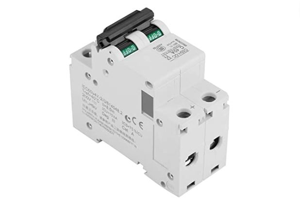
أنواع الصمامات في تبديل عازل التيار المستمر
يعد استخدام مفاتيح عزل التيار المستمر إلى جانب الصمامات أمرًا شائعًا في توفير الحماية من التيار الزائد في دوائر التيار المستمر. تعمل الصمامات على قطع الدائرة عند مرور التيار الزائد مما يحمي النظام الكهربائي والمكونات من التلف.
تشمل أنواع الصمامات المستخدمة عادةً مع مفاتيح عزل التيار المستمر ما يلي:
- صمامات الشفرة:تتوفر أجسام بلاستيكية ذات شفرات معدنية متعددة متصلة بحوامل الصمامات في تصنيفات تيار مختلفة.
- صمامات الخرطوشة:هي عبارة عن صمامات أسطوانية تتكون من عنصر صمام محاط بجسم غير موصل وتستخدم عادة في التطبيقات التي توفر مجموعة من تصنيفات التيار.
- الصمامات الكهروضوئية: تحمي الصمامات الكهروضوئية الأنظمة الكهروضوئية القادرة على التعامل مع الجهد والتيارات المستمرة العالية مع تبديد الطاقة المنخفض.
استخدامات مفتاح عزل التيار المستمر
تُستخدم مفاتيح عزل التيار المستمر في العديد من الصناعات والأنظمة لفصل وعزل دوائر التيار المستمر. ويختلف الاستخدام في هذه الحالات وفقًا للمتطلبات المحددة مثل تصنيف الجهد والتيار ومعايير التطبيق.
تتضمن بعض التطبيقات الشائعة ما يلي:
i. أنظمة البطاريات
الوظيفة الأساسية لمفتاح عزل التيار المستمر في أنظمة البطاريات هي فصل البطارية عن النظام الكهربائي. عندما يكون المفتاح في وضع إيقاف التشغيل، فإنه يقطع تدفق التيار الكهربائي من البطارية ويعزلها بشكل فعال. مثل هذه الأنظمة البطارية شائعة في المركبات والسفن البحرية.
يمنع العزل استنزاف الطاقة المستمر من البطارية في حالة خمول النظام أو بدلاً من ذلك أثناء التخزين أو الخضوع للصيانة. وبالتالي، يحمي مفتاح عزل التيار المستمر البطارية من التفريغ المفرط الناتج عن الأحمال الطفيلية أو الأعطال التي تطيل عمرها.
2. الأنظمة الكهروضوئية
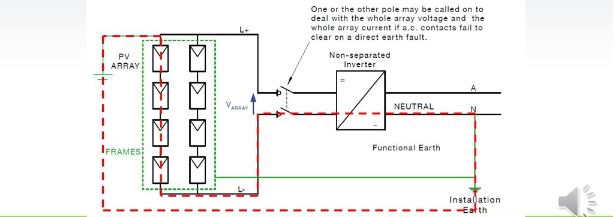
تستخدم أنظمة الطاقة الكهروضوئية (والأنظمة الشمسية أيضًا) مفاتيح عزل التيار المستمر في عزل الدائرة وفصلها عن النظام. وهذا يضمن تشغيل وصيانة تركيبات الطاقة الشمسية بأمان حتى في حالة الطوارئ.
يوفر مفتاح عزل التيار المستمر الكهروضوئي وسيلة لعزل الطاقة المستمرة المولدة بواسطة تركيب الطاقة الشمسية. فهو يفصل النظام الشمسي عن وحدة التحكم في الشحن أو العاكس مما يحمي سلامة الأفراد أثناء عمليات الإغلاق الطارئة وأنشطة الصيانة.
ثالثا: لوحات التحكم الصناعية
عند استخدامها في لوحات التحكم الصناعية، توفر مفاتيح عزل التيار المستمر عزلًا لطاقة التيار المستمر للمحركات ومحركات الأقراص. يعد تقييد إمداد الطاقة لهذه المعدات الكهربائية ضروريًا للسماح بإجراء إجراءات الصيانة الآمنة والتعامل مع حالات الطوارئ.
رابعا: مراكز الاتصالات والبيانات
في أنظمة الاتصالات، تعمل مفاتيح عزل التيار المستمر على فصل معدات الاتصالات عن مصادر الطاقة المستمرة مثل المقومات ومجموعات البطاريات. عند التعامل مع مراكز البيانات، توجد مفاتيح فصل التيار المستمر في أنظمة توزيع الطاقة لأنظمة النسخ الاحتياطي.
خاتمة
قد تختلف المعايير والمتطلبات الخاصة بمفاتيح عزل التيار المستمر حسب التطبيق وتصنيفات الجهد والتيار للنظام. ومع ذلك، فإن الالتزام بالمعايير واللوائح الكهربائية المحلية يضمن أن تركيب مفتاح عزل التيار المستمر الخاص بك آمن وموثوق.


